Shearography, a useful non-invasive optical metrology for structural testing and qualifications!
- Koohyar Pooladvand

- Aug 7, 2021
- 4 min read
Introduction
Shearography or Speckle pattern shearing interferometry is a full-field non-contact optical technique, usually used for the qualitative measurement of changes in the displacement gradient caused by surface and subsurface defects. A speckle pattern is formed by illuminating an optically rough surface with an expanded laser beam. In shearography, this speckle pattern is optically mixed with an identical but displaced, or sheared, speckle pattern using a shearing device, and viewed through a lens, forming a speckle interferogram at the camera surface.
The shearing device commonly used for shearography is a Michelson interferometer with a tilt applied to one of the mirrors. Correlating speckle interferograms obtained before and after object deformation yields correlation fringes sensitive to displacement gradient in the shear direction. Phase-stepping techniques are often used to extract phase information and, therefore, the displacement gradient information from speckle interferograms.

Fig. 1. A typical shearography system based on
a Michelson interferometer.
What makes shearography an interesting option for a wide range of test and qualification is its low sensitivity to environmental disturbances. In this technique a high-pass filter is used and the rate or slope of changes are measured directly not the deformation or displacement as in holographic based measurements. One can imagine this technique is used for qualification of shafts or large structures to find the location of cracks or weaknesses in a structure round which a high rate of strain or deformation is expected. Shearography requires coherent light, however, light is only projected to the area of interest and the reflection light passes through a Mickelson interferometer to interfere with itself while a small shear to the one of the reflected light contributes to the interference patterns form on the detector of a camera. This is a secret recipe that makes this system less sensitive to environmental disturbances and frontrunner for a large field of view industrial applications.
Basics of shearography
Interference
In a shearography system, two slightly spatially shifted speckle fields of the rough surface are superimposed. If the two wave fields are separated laterally by mutual shearing, two nearly collinear wave fields are obtained.

This is considered the reference state of the object. Deformation of the object leads to change of the phase Δϕ(x,y) of wave fields:
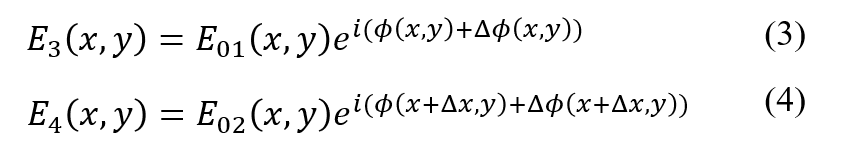
The superposition of each pair produces interference patterns corresponding to reference and deformed states:

The reference and deformed states, I_A and I_B, are digitized via CCD camera. ψ(x,y) is the randomly distributed phase difference of the two wave fields. Through phase stepping techniques we can obtain the phase change Δϕ(x,y), that is related to the object deformation as follows:

The above simplification accounts for sensitive vectors of the system relative to the object. This makes the system sensitive to the slope of out-of-plane deformation δw/δs of the object in the direction of shear δs. By adjusting the optical setup for a horizontal or vertical shear δs= δx, δy , the system can record the horizontal and vertical slope of the out of plane deformations of the object.

Fig. 2. Arrangement for digital shearography Optical Head.
This allows to quantify individual components of the strain tensor of the object surface at any measurement point.

Temporal Phase Unwrapping
Many phase unwrapping algorithms have limited capabilities to the analysis of interferometric images of objects containing physical discontinuities. Temporal phase unwrapping algorithms can overcome this limitation.
•The evaluated interference phase distributions are ambiguous in having only values between −π and +π. Although in most practical applications a continuous interference phase distribution is expected
2π-discontinuities are resolved by adding a step function consisting only of 2π –steps
The basic idea behind the proposed method is that the phase at each pixel is measured as a function of time
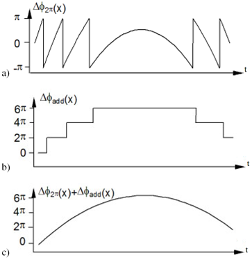
Fig. 3. Demodulation: a) interference phase modulo 2π, b) step function to be added, and c) unwrapped interference phase distribution [4].
Due to expected large optical phase variations in this application, which constrain the use of spatial phase unwrapping, One can develop and implement a temporal phase unwrapper for real-time measurements. The basic idea behind the method is that the phase at each pixel is measured as a function of time. Unwrapping is then carried out along the time axis for the analysis of each pixel independent of its neighbors with the assumption that deformations occur slower than the frame rate of acquisition. Therefore, the number of discontinuities is calculated by computing the fringe order, N(x,y,t), between two consecutive frames with
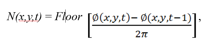
where Ø(x,y,t), is the optical phase at pixel (x,y) in the t-th frame for t = 0, 1, 2, . . ., n. So, the total number of discontinuities, up to the n-th frame in the time axis, is calculated as

Next, 2πT(x,y,n) is added to Ø(x,y,t), to obtain the unwrapped phase of the n-th frame. Such a temporal phase unwrapping has the potential to directly compute continuous optical phase for the investigation of components in real-time.
Shearography applications
Different sheaograohy based qualification and non-destructive tools are used widely in aerospace, automotive, renewable energy, defense, marine, and art conservation. Shearography can identify local defects that are common in structures or components such as elimination, crack, and wrinkle in composite materials.
This method also finds its application in realm of additive manufacturing where bonding quality, porosity, local crack, fluid ingress, and hidden defects in large 3D printed components become of critical importance where other methods like CT are not practical. in addition, shape complexity, material, and geometry is not a concern for shearography based inspection tool that gives this technique a big advantage for being used in AM component qualification.
This tool can be used for the following applications:
quality of different materials,
strain measurement,
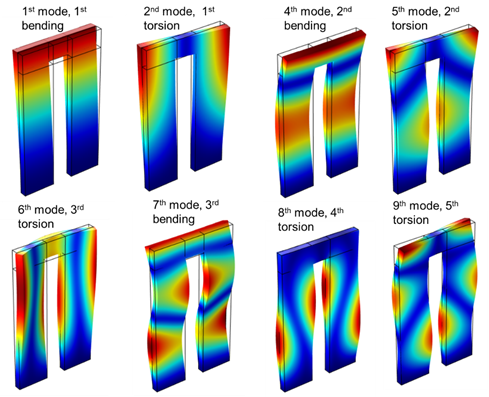
vibration analysis
structural health analyses for large area testing
composite nondestructive testing
Like any other non-destructive technique, shearography is not a perfect solution and has some inherent disadvantages such as,
needs excitation such as thermal, magnetic, and force that can be expensive or damage the object of interest
not a suitable method for smooth surfaces like glass, mirror, or polished with the roughness less than the wavelength of the light source
complex fringes and interferences that make the interpretation of the data difficult.
References:
Center for Holographic Studies and Laser micro-mechaTronics (wpi.edu)
MK Meybodi, I Dobrev, P Klausmeyer, EJ Harrington, C Furlong, "Investigation of thermomechanical effects of lighting conditions on canvas paintings by laser shearography", SPIE Optical Engineering+ Applications, 2012

Comments