Modal analysis and 3D printing, how plate theory (Kirchhoff-Love ) helps 3D printing!
- Koohyar Pooladvand

- Oct 3, 2021
- 6 min read
Introduction
Cantilever and constrained plates and beams have been employed for analyses of the mechanical properties and have proven to be practical for estimating isotropic, orthotropic, and anisotropic elastic properties of different materials [1, 2-5]. The applied approaches also measured the natural frequencies of the vibrating object to evaluate the elastic moduli in complex multi-layer structures, such as composite materials, which lent itself to additively manufactured plates and beams. L. Gaul et al. [6], and Pryputniewicz [7] utilized full-field-of-view optical sensors to improve the accuracy of moduli estimation and to estimate the Poisson’s ratio directly from mode shapes.
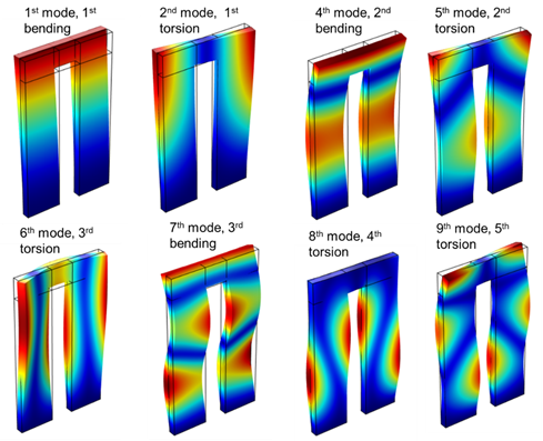
The mode shapes for the natural frequencies of a cantilever beam.
Besides, the American Society for Testing and Materials (ASTM) established standards number E-1875 and E-1876 to explain the procedure of evaluation of the dynamic mechanical properties through modal analyses. However, these methods may not be practical to estimate residual stresses, although there have been attempts to estimate the presence of residual stresses in plates using vibrational techniques.
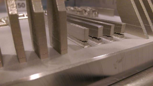
Anisotropicity is one of the challenges associated with 3D printed components; this characteristic appears to be directionally and geometrically dependent. One can examine plate theory (Kirchhoff-Love theory) by designing a testing artifact with different thicknesses.
With these criteria in mind, we explain below general plate theory and the principles of designing a testing artifact capable of evaluating mechanical properties through modal analyses.
Design consideration for testing artifacts for modal analyses
The transverse displacement in an isotropic plate is defined according to the following partial differential equation (PDE):

where, t is Γ time, transverse displacement, σp= ρ×h plate area density, ▼² Laplace operator, and D flexural rigidity is defined as:

where E is Young’s modulus, h plate thickness, and ν Poisson’s ratio. The solution of this PDE is sought in the form Γ(x,y) e^iωt of by finding the ω satisfying the following equation:

The mathematical and numerical approach to solve this differential equation has been elaborated by G.B. Warburton and A. W. Leissa [8, 9] with the general solution for isotropic material in the Cartesian coordinate system found as a Fourier series as:
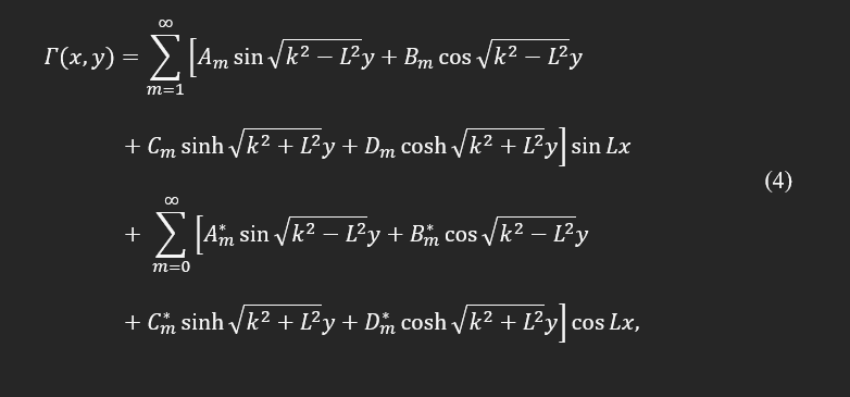
In the above equation, L is the length of the rectangular plate and k^4=ρω²/D . In the proposed methodology, the natural frequencies of the cantilever plate are the target of interest and obtained as:
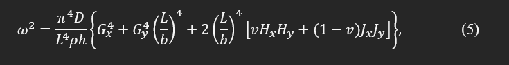
Gx, Gy, Hx, and Hy are constant coefficients as explained by A. W. Leissa [8] and G. B. Warburton [9]. These series of constants depend on boundary conditions, geometry, mode number, and Poisson's ratio.
There are several references dedicated to analytically calculating and experimentally measuring these eigenvalues for different boundary conditions and geometry, specifically for a square or rectangular plate; for example, D. Young [10], W. V. Barton [11], and N. W. Bazely et al. [12] investigated these constants.
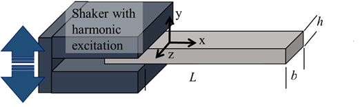
Fig. 1. Representative of the cantilever beam, the boundary condition, dimensions, and the shaker for experimentally determination of the 3D printed testing artifacts.
Rewriting the Eq. (5) in the following format indicates that the non-dimensional eigenvalues for each mode and known boundary condition can be represented only as a function of geometrical characteristics and Poisson's ratio.
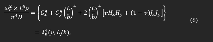
where, λn is a non-dimensional eigenvalue of the plate. It also suggests that the ratio between frequencies is equivalent to their corresponding eigenvalues; such a hypothesis was used in a design on the Poisson’s test plate (Resonalyser procedure) to estimate the Poisson’s ratio directly from two natural frequencies. In addition, the ratio between different natural frequencies can only depend on the Poisson’s ratio. Such a dependency was defined as third-order polynomials and was applied to find the isotropic material properties.
One can analytically seek a solution of Eq. (3) for a simplified geometry, such as a rod or reed with constant cross-section and known geometry, and estimate natural frequencies and mode shapes. For a solid cantilever beam, as shown in Fig. 1, the analytical solution is available in the following terms:

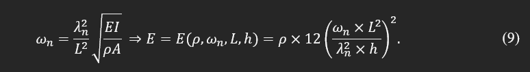
Finding a module of elasticity in a simplified case of a long cantilever thin plate with a large L/b ratio and isotropic property can be formulated based on the natural frequency (ω), density (ρ), and dimensions as:

If the sample is a beam with a fixed area, the module of elasticity can be found as:
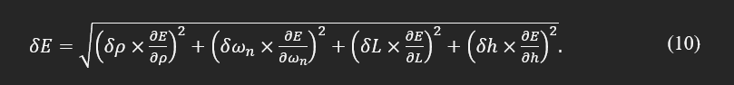
Considering the above definition, the uncertainty in the calculation of the module of elasticity can be found:
Torsional mode and natural frequencies of testing artifacts with isotropic material
The torsional vibration of a beam with a known and constant cross-section is defined based on the angular displacement along the length of the beam. The following equation defines the governing equations for bar, beam, and rod objects:
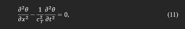
where θ is angular displacement, and CT is torsional wave speed. This speed for an isotropic object depends on shear modulus, G, density, ρ, polar moment of inertia, Ip, and factor χ as defined in the following equation:
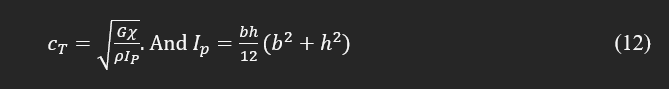
The factor χ is similar to λ, which depends on the geometry, and for a rectangular cross-section (shown in Fig. 1) can be theoretically found as:

The frequency and wavenumber for a cantilever torsional vibration are:

Testing artifacts with orthotropic materials
If the artifact has orthotropic properties, the transverse differential equation of the motion is defined as:
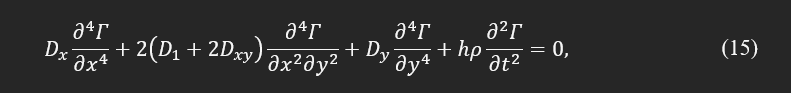
where:

In this case, the natural frequencies can be determined by:
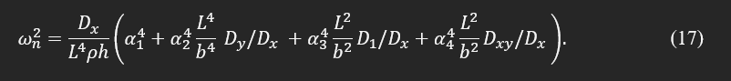
For different boundary conditions, it is challenging to determine α1, α2, α3, and α4 analytically. However, the solution for a specific shape of interest, i.e., beam or plate, can be found computationally or estimated experimentally. It can be shown that the following equations are derivable from the bending stiffness (Dx,Dy, and D1) and torsional stiffness (Dxy) as:

The laminated composite theory was applied to estimate the mesostructure properties of the printed components for FDM technology. Authors suggested transversely isotropic material properties and found the 6 independent material constants knowing the fiber elastic modulus and porosity as:
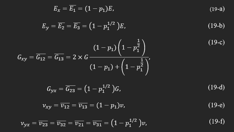
where E is the module of elasticity, G is shear moduli, ν is the Poisson’s ratio of the pristine bulk filament, and p1 is the void density of plane 1 with normal along x1. If the print direction is assumed to be rectilinear along the length of the object, then principle directions 1 and 2 are along the x and y directions of the specimens, respectively. This approximation was able to predict the material properties with a maximum of 10 percent error compared with experimental measurements. Porosity, p1, is a critical parameter depending on infill and printing strategy. It can change between minimum theoretical 0, in a perfect bonding with zero void between filaments, to about 90 percent with the lowest possible infill. However, this value in the case of a solid printing option in FDM printers changes from 0 to 1-π/4.
In addition to the effect of voids, an empirical factor was also introduced to account for the imperfect bonding between two adjacent filaments and known as effective load-carrying potentials of the 3D printed components. This factor, which changes between 0 to 1, with a typical value of 0.85, multiplies to the predicted theoretical values to reflect the imperfect circumstances.
References
[1] Alfano, M., and Pagnotta, L., 2006, "An Inverse Procedure for Determining the Material Constants of Isotropic Square Plates by Impulse Excitation of Vibration," Applied Mechanics and Materials, 3-4, p. 287.
[2] Frederiksen, P. S. J. J. o. C. M., 1997, "Experimental procedure and results for the identification of elastic constants of thick orthotropic plates," 31(4), pp. 360-382.
[3] Pedersen, P., and Frederiksen, P., 1992, "Identification of orthotropic material moduli by a combined experimental/numerical method," Measurement, 10(3), pp. 113-118.
[4] Larsson, D., 1997, "Using modal analysis for estimation of anisotropic material constants," Journal of engineering mechanics, 123(3), pp. 222-229.
[5] Lai, T., and Lau, T., 1993, "Determination of elastic constants of a generally orthotropic plate by modal analysis," International Journal of Analytical and Experimental Modal Analysis, 8, pp. 15-33.
[6] Gaul, L., Willner, K., and Hurlebaus, S., "Determination of Material Properties of Plates from Modal ESPI Measurements,# 5," Proc. PROCEEDINGS-SPIE THE INTERNATIONAL SOCIETY FOR OPTICAL ENGINEERING, SPIE INTERNATIONAL SOCIETY FOR OPTICAL, pp. 1756-1762.
[7] Pryputniewicz, R. J., "Time Average Holography In Vibration Analysis," SPIE, p. 6.
[8] Leissa, A. W. J. V. o. p., 1969, "NASA SP-160," pp. 59-60.
[9] Warburton, G., 1954, "The vibration of rectangular plates," Journal Proceedings of the Institution of Mechanical Engineers, 168(1), pp. 371-384.
[10] Young, D. J. J. a. M., 1950, "Vibration of rectangular plates by Ritz method," 17, pp. 448-453.
[11] Barton, M. J. J. O. A. M.-T. O. T. A., 1951, "Vibration of rectangular and skew cantilever plates," 18(2), pp. 129-134.
[12] Bazley, N. W., Fox, D. W., Stadter, J. T. J. Z. J. o. A. M., and Mechanik, M. Z. f. A. M. u., 1967, "Upper and lower bounds for the frequencies of rectangular cantilever plates," 47(4), pp. 251-260.
[13] Pooladvand, K., 2019, "Multifunctional Testing Artifacts for Evaluation of 3d Printed Components by Fused Deposition Modeling," Worcester Polytechnic Institute, [Link].


Comments