How non-invasively measure residual stresses in thin 3D printed objects in MEMS
- Koohyar Pooladvand

- Aug 14, 2021
- 3 min read
Introduction
The cantilever deflection method has been used to estimate the residual stresses in thin-film specimens; this method draws on beam theory and measures the curvature of the cantilever beam non-invasively. A similar concept was also applied for the estimation of residual stresses in plastic injection-molding specimens with relatively thick plastic bars.
Anisotropicity is one of the challenges associated with 3D printed components; this characteristic appears to be directionally and geometrically dependent.
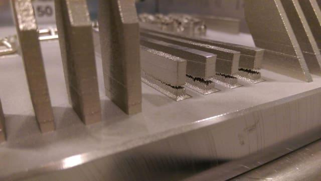
Stress has caused these metal bars to crack during the powder bed process. (Image from the University of Pittsburgh’s Swanson School of Engineering.) Credited to Engineering.com
Design considerations for testing artifacts for residual stress estimation
The curvature of a beam relates to the applied moment and distribution of stresses, which can be explained with the Euler–Bernoulli beam theory. For a beam illustrated in Fig. 1, the following equation defines a mathematical representation of the theory by relating the curvature, structural, and material properties of the beam to applied forces and moments:
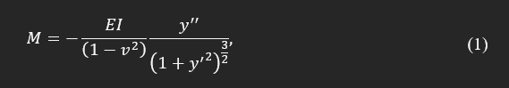
where M is bending moment, I is flexural stiffness of the beam, y is the beam normal deflection, ν is Poisson’s ratio, and E is a module of elasticity. In the case of small curvature, the magnitude of y' is negligible compared to 1.0, and this equation becomes analytically solvable. Equation (1) can also be rewritten in terms of local curvature as:
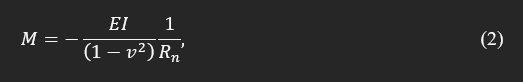
where, Rn curvature is ((1+y'^2)^3/2)/y'' which can be alternatively defined as (δ^2 + L^2)^3/2 /2δ where δ is the measured deflection in a particular length of the specimen, L. It has to be noted that the latter approximation is valid if the deflection is small compared to the length of the beam.
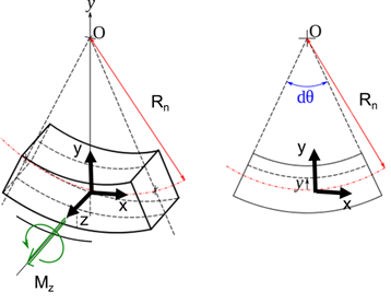
Fig. 1. The representation of the Euler-Belnoli beam with constant cross-section subjected to moment in the z-direction.
To capture the effect of residual stresses by measuring the curvature, it is recommended to have the length of the diagnostic structure 5-10 times larger than the thickness of the areas subjected to residual stresses.
Integration of normal stress over the cross-section mathematically defines the applied moment. These normal stresses in the section can be expressed in terms of two stresses, mean and gradient stresses. This definition is constructed as the summation of polynomials as follows:

where, σm in mean stress, and σk is gradient stress, and ak is a constant relating to the cross-section; for example, for k=1 in a rectangular section with height h, this is a1=2/h. y is the distance between the fiber and neutral axis.
For nano- and micro-scale components, deposition of a thin layer of dissimilar material causes the substrate to distort, and if layer thickness satisfies thin-layer criteria, the introduced stresses to the substrate can be estimated according to the following equation, as described elsewhere [223-225]:
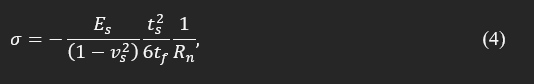
where σ is biaxial stress in the film, subscript s indicates the substrate, f indicates the thin layer, t is the thickness, and the rest as defined previously. In case the thickness of the deposited layer does not satisfy the thin-layer approximation, Brenner et al. [7], and K. Roll [8] suggested the following corrected equation:
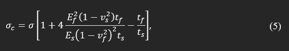
where σc is the corrected version of the preliminary estimation of σ, and the rest are defined in previous equations. Since the deposition in 3D printed features specifically in MEMS or electroforming process is conceptually similar to layer deposition, an analogous approach can be adopted for the estimation of residual stresses, knowing curvature and cross-sections of a 3D printed beam.
References
[1] Berry, B., and Pritchet, W. J. J. o. a. p., 1990, "Internal stress and internal friction in thin‐layer microelectronic materials," 67(8), pp. 3661-3668.
[2] Pham, H. T., Bosnyak, C. P., and Sehanobish, K., 1993, "Residual stresses in injection molded polycarbonate rectangular bars," Polymer Engineering & Science, 33(24), pp. 1634-1643.
[3] Stoney, G. G. J. P. R. S. L. A., 1909, "The tension of metallic films deposited by electrolysis," 82(553), pp. 172-175.
[4] Nix, W. D. J. M. t. A., 1989, "Mechanical properties of thin films," 20(11), p. 2217.
[5] Baker, S. P., and Nix, W. D., "Mechanical properties of thin films on substrates," Proc. 34th Annual International Technical Symposium on Optical and Optoelectronic Applied Science and Engineering, SPIE, p. 14.
[6] Saif, M., Hui, C., and Zehnder, A., 1993, "Interface shear stresses induced by non-uniform heating of a film on a substrate," Thin Solid Films, 224(2), pp. 159-167.
[7] Brenner, A., and Senderoff, S. J. J. R. N. B. S., 1949, "Calculation of stress in electrodeposits from the curvature of a plated strip," 42(105), pp. 105-123.
[8] Röll, K. J. J. o. A. P., 1976, "Analysis of stress and strain distribution in thin films and substrates," 47(7), pp. 3224-3229.
[9] Pooladvand, K., 2019, "Multifunctional Testing Artifacts for Evaluation of 3d Printed Components by Fused Deposition Modeling," Worcester Polytechnic Institute, [Link].


Comments