Residual Stress in AM parts
Residual stress is the state of stresses in a component not because of any external load but as a result of the current interactions of the locally distributed stresses in the part as in its present equilibrium condition. The part that has residual stresses may not be distinguishable based on its shape and appearance, but the stresses inside the part have significant effects on its functionality, endurance, fatigue life, and performance. Residual stress can arise from differences in thermal expansion, yield stress, or stiffness.
There are three main causes for residual stresses: the mismatch of coefficients of thermal expansion (CTE), the plastically induced misfits, and the phase change or chemical generated misfits as shown in Fig.1. In the nonlinear structural environment, expansion and contraction of the material due to phase change and temperature differences interact with material elastic-plastic behavior to develop stress/strain distribution that may deform components.

Fig. 1. Residual stresses can develop in part because combination of these potential sources: Phase transformation, thermal gradient and CTE mismatch, and inelastic deformation. Source: K.P. Dissertation
There are various techniques to measure residual stresses. These techniques can be categorized into three groups: destructive, semi-destructive, and non-destructive. Measuring elastic strains in the atomic lattice plane of crystalline material is a Non-destructive method to estimate the residual stresses accurately. X-ray diffraction, neutron diffraction, and synchrotron X-ray are three well-known non-destructive methods based on atomic lattice plane measurements. Although these methods are accurate, they have some disadvantages, for example, limited penetration depth up to some centimeters in steel, the price and size of the equipment, hazards to operators, and their limited availability to specific and secure areas, i.e., atomic reactors in neutron diffraction. These disadvantages circumscribe the applications and effectiveness of these methods for practical usages.
Destructive methodologies are those that depend on the stress relaxation that happens after removing the material locally. Any changes in the current equilibrium condition cause the part to reach a new equilibrium status, and measuring the changes leads to the estimation of residual stresses. These changes are usually subtle, especially when the material has a high module of elasticity, i.e., steel that requires precise measuring tools. Sectioning, and the contour method are two popular destructive methodologies. One of the main difficulties with these methods is the sacrification of the components to estimate residual stresses. This scarification consumes time, energy, and resources and may not be applicable to all cases, specifically in additive manufacturing, when the 3D printed part is expensive.
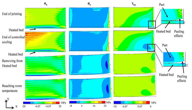
Fig. 2. Computationally predicted contour plots of three principal residual stresses in a 3D printed bar by FDM/FFF, at four critical instances, including end of printing, end of controlled cooling attached to the heated bed, removal from the heated-bed, and after reaching room temperature. Simulations can be used to predict peeling of the part from the heated bed. . Source: K.P. Dissertation
The most common and well-accepted tools for measurements of residual stresses are semi-destructive methods. In these methods, instead of cutting through the part or removing a portion of the structure, a tiny hole is drilled on the surfaced that can be successively continued to measure averages of residual stresses on different depths in the component under investigation. In some other similar techniques, local relaxation due to thermal or laser ablation can be performed instead of hole drilling.
The accuracy of these techniques is less than diffraction methods, but the setups are reliable and versatile and can be used for the measurement of different materials, either crystalline or amorphous, in different conditions. Most of the modern measuring tools, in contrast to old ones using strain rosette, are based on full-field optical measurement using different methodologies such as Holographic Interferometry (HI), Digital Speckle Pattern Interferometry (DSPI), or Digital Image Correlation (DIC). However, these require a high level of understanding of the physics of the residual stresses, knowledge of the optical techniques, and preparation of the surface or drilling tools. Nonetheless, DIC among the other tools is more user-friendly and less complex, but the sensitivity of the system, specifically in stiff material, limits the application of DIC for residual stress measurements. For more information contact Center For Holographic Studies and Laser micromechaTronics (CHSLT) at WPI.

Fig. 3. Holographic setup for measuring the in-plane deformation during incremental hole-drilling to estimate the residual stresses. Source: K.P. Dissertation
A few indirect methods have been developed to estimate the residual stresses, specifically in thin films, MEMS, and NEMS devices. These indirect methods rely on the mechanical properties, shape, and curvature of a specimen that can be measured during fabrication or afterward. In these techniques, distortion is associated with residual stresses; for example, by measuring the curvature of a cantilever beam, one can estimate the level of stresses.
Hole Drilling for Residual stress measurements
Among the mentioned methods, hole drilling due to its simplicity, accuracy, and effectiveness along with its minimal effect on the part structural integrity was implemented more. The process of hole drilling method for measurement of residual stresses is simply defined by precisely removing the small portion of the material from the surface, measure the deformation/strain after removal, and solve an inverse problem to obtain the average of residual stresses.
Hole-drilling for measuring residual stresses, Source: Hill-Engineering.com
Deep Hole Drilling (DHD) for measuring residual stresses. Source: veqter.co.uk
There are several methods developed to relate displacement field to residual stresses, one of the most practical was proposed by Schajor that takes advantage of using finite element method along with non-invasive optical metrology methodology called Digital Speckle Pattern Interferometry (DSPI).
By knowing the anticipated range of residual stresses, it is possible to theoretically estimate the fringe formation for in-plane DSPI. This process helps to estimate the fringes if the magnitude of residual stresses is known and adjust the system to be able to perform accurately for the target range of stresses as shown in Fig. 4.
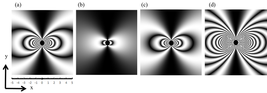
Fig. 4: Computer generated fringes for in-plane DSPI sensitive to x-direction around a drilled hole with a radius equal to 0.8 mm in a thin plate for different biaxial stress state: : (a) σx=-3.8MPa; (b) σx=0.5MPa; (c) σx=2.0MPa; (d) σx=11.0 MPa. Source: K.P. Dissertation
If the magnitude of residual stresses is large enough, even the best-designed DSPI system may not have enough resolution to capture the dense fringes forms around the hole as shown in Fig. 4-a & d. Thus other methods, i.e., DIC also is applicable for displacement measurements with lower resolution that offers better potential for measurement strain.