How to Employ Finite Element Method (FEM) for FDM 3D printing
- Koohyar Pooladvand

- Apr 4, 2021
- 6 min read
Updated: Aug 18, 2021
Numerical modeling is a powerful tool to predict and optimize processes for 3D printing. The computational model is complex and challenging; however, in technologies like FDM, it can be simplified using state-of-the-art numerical simulators like ANSYS (R) or ABAQUS (R).
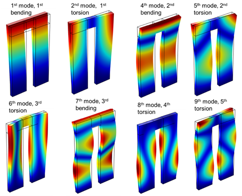
This software can be used to achieve results like the one shown below.
This post describes a concept of developing such a numerical model in ANSYS. It starts by choosing the right element. It is recommended to use higher-order elements, i.e., quadratic ones, instead of linear elements with more than two nodes on each edge to get better results. Printing layer-by-layer is 3-dimensional phenomena, and the numerical model intends to investigate the process must be modeled as such. In this post, a concept of a 2D model is explained which can be expanded to a 3D model. Model is based on a 2D mesh using a mapped quadrilateral grid as shown below. FEM software like ANSYS(R) has built-in capability known as element activation aka element birth/death technology allowing a progressive activation/deactivation of elements resembling layer-by-layer deposition in 3D printing.

The crucial step in the uncoupled thermo-mechanical model is an accurate and reliable estimation of thermal flow and temperature distributions. Thus, we took into account the dependency of material properties on temperature, specifically conductivity, specific heat capacity, and convection-radiation heat dissipation. Due to the presence of porosity and cavity in 3D printed components as a result of spatially varying bonding and welding, conductivity can change from fully welded locations to places with less and undeveloped bonding between filaments. One has to account for both temporal and spatial changes in conductivity and other material properties to be able to capture the thermal complexity of FDM realistically. This complexity is caused by counter effects between, on the one hand, temperature and printing history and, on the other, time and development of bonding.
Since the deformation is expected to be large compared to the size of the component, as shown below, large-deformation analyses were active, for which, instead of engineering stress-strain constitutive equations, the Cauchy stress-strain constitutive model was used.

Material and contact modeling in ANSYS
There are various models available in ANSYS ADPL for different attributes in materials. Models such as linear elasticity, multiyear elasticity, nonlinear elasticity, large deformation elasticity (hyperelastic), small deformation plasticity (Elasto-plastic), pressure-dependent plasticity (Drucker Prager/ Extended Drucker Prager), rate-dependent plasticity (viscoplasticity), Bergstrom Boyce, viscoelastic, and creep can be defined in ANSYS. Furthermore, the material response to applied loads can be defined through different material constitutive models such as isotropic, orthotropic, and anisotropic considering behaviors such as elastic, elasto-plastic, isotropic hardening, kinematic hardening, generalized Hill, Drucker-Prager, and Gurson. These models and material properties are integrated into FEA material libraries of ANSYS APDL.
Assuming an elastic material model], one can capture the thermo-mechanical complexity in FDM, but plasticity has to be added to accurately estimate stresses and preclude the presence of the exaggerated residual stresses beyond the yield point. Some researchers also modeled viscoelastic material based on Prony series by curve fitting the available experimental data in an attempt to evaluate the effect of weight and gravity due to stacking on the lower layer of polymeric 3D printed components. They did not report significant deformation due to weight using this viscoelastic model.

We suggested a temperature dependent elasto-plastic behavior to represent the material properties in our FE analyses. We assumed a monotonical increase in stress-strain behavior, although, some polymers (e.g., ABS) exhibit softening after yield stresses before retaining hardening.
However, this softening has not been reported for printed components with ABS and PEEK elsewhere, and we did not observe it in our micro tensile-test (shown above). Kinematic hardening or a combination of kinematic and isotropic hardening has been recommended for material models. Isotropic hardening was selected for plastic deformation considering the dearth of the experimental data and the possibility of reversal plastic deformation. Polymeric materials usually have a nonlinear stress-strain behavior that fits a multilinear stress-strain curve; although it was possible to model the material using the multilinear stress-strain curve, we avoided that complexity and assumed bilinear plasticity by applying Bilinear Isotropic Hardening (BISO) model as shown below.

Temperature is a critical parameter in transient thermo-mechanical phenomena, affecting properties such as conductivity, thermal heat capacity, and density. Whereas, it is recommended to account for the changes in thermal heat capacity and associated variation in latent heat close to Tg. Enthalpy formulation, as described in below equation was used for modeling the latent heat in this numerical model.

where hp is enthalpy, is specific heat, and T is temperature. Parameter Cp is defined as a function of temperature; and its value changes sharply around glass transition temperature and reduces after passing this point.
In addition to the model properties for the polymers, setting up the specification of the layer connecting the components to the build-plate is challenging too. Some researchers have applied a fixed boundary condition that could potentially result in physically unjustified stresses and distortion. The fixed boundary condition is rarely applied to constrain the object during printing in FDM, and the contact between polymer and the build-plate is always a location of the interaction of two dissimilar materials. We decided to simulate this contact as an adhesion contact layer. ANSYS APDL offered a variety of different material models and contact element technologies to do so. These models and technologies mathematically define and evaluate the interaction of dissimilar or similar materials. In our model, we used the cohesion model by defining surface-to-surface contact between the polymer and the heated bed. In particular, the Cohesive Zone Material (CZM) model was defined to predict the interface mechanics. The CZM model showed a bilinear behavior and allowed two ways to specify material data with tractions and separation distances.
Summary of simulating thermal and thermo-mechanical
Modeling of the process was complicated and multidisciplinary, and the following conceptual assumptions were made in the FEM model to carry out the simulations:
the process, in general, was considered thermally driven, and in order to estimate the distortion and residual stresses, an uncoupled thermo-mechanical model was developed where the thermal problem was solved first and then applied as loads to thermo-mechanical model,
the higher-order quadratic element was used for both thermal and thermo-mechanical models,
some essential material properties such as a module of elasticity, yield stress, and specific heat were considered temperature dependence,
radiation was incorporated as a total heat transfer coefficient in the thermal model,
boundary conditions such as convection and radiation heat transfer were considered temperature dependent,
the current deposited layer was deemed to be at the same temperature assigned to the extruder head,
2D thermo-mechanical simulation was simulated assuming plane strain condition by introducing the depth of the element,
the manufacturing process was continuous; however, it was simulated step-wise such that at each step deposition of the new bead was modeled by activation of those elements that composed deposited volume; this process was known as element activation or birth/death strategy and applied to both thermal and thermo-mechanical models,
contact element was introduced between the polymer and heated bed to replicate the cohesion interfaces,
time step was assumed based on the equivalent time for the deposition of the whole width of the sample in the 2D thermal model,
the deposited volume was commensurate to deposition length reached with average machine linear velocity (U) in the given time step,
the new elements that belonged to the newly deposited volume were activated entirely at the beginning of time step,
the layers were defined by incrementally adding a batch of elements to reach the final set of elements,
the effect of gaps and voids was applied as a correction factor to density, for connectivity.

The model consisted of two different physics with the same geometry but corresponding material properties and element types. The chosen elements were higher-order solid 8-node quadrilaterals with PLANE77 and PLANE183 being used for thermal and structural analysis, respectively. The half-length of the sample is modeled by assuming the symmetry condition on the centerline. The geometry with the applied boundary conditions is shown in above Figure (b).
In order to model the nature of the continuous adding material, the birth/death feature in ANSYS was utilized. Figure (a) illustrates our approach for the simulation of the deposition in Cartesian coordinates. On the current layer, deposition was simulated by progressively activating a set of elements, the purple set, in the direction of the extruder movement, as shown in Figure (a) above; the tool-path defined the deposition strategy. For example, Figure (c) shows deposition as the extruder moves from right to left on the first layer and reversely on the next layer above. This process was repeated until the final layer was deposited after which the simulation continued in order to evaluate the cooling process and the removal of the part from the heated-bed.


References:
[1] Pooladvand, K., 2019, "Multifunctional Testing Artifacts for Evaluation of 3d Printed Components by Fused Deposition Modeling," Worcester Polytechnic Institute, [Link].

Comments