Convection heat transfer in 3D printing, how to estimate, and where to include it?
- Koohyar Pooladvand

- Jun 27, 2021
- 7 min read
Updated: Aug 18, 2021
Convection heat transfer plays a vital role in thermal flow in different 3D printing technology such as FDM. The coefficient of convection heat transfer is a function of Reynolds number, material properties, and the average temperature of envelope and surface temperature. The size and velocity play an essential role in the Reynolds number, and it has to be taken into account when dealing with a different scale.
On the other hand, looking closely at the nature of the heat transfer also indicates the process has to be considered on two levels: filament and part levels. While in the filament level, the size of the nozzles changes from 0.2 to 14 mm; in part level, the size changes from 1 to 1,000 mm or even larger.
Required adjustment for the coefficient of heat transfer in different levels
One may suggest the applied boundary conditions have to be adjusted based on specific criteria such as size, velocity, location, and temperature. We suggested the following procedure to be applied to the convection heat transfer coefficient:
The filament level (Micro-level)
Top layers or machine with the enclosed heating system (Meso-level)
Other layers and open 3D printers (Macro-level)
Desktop or industrial 3D printers are available in both open or closed chambers. Some of the more advanced FDM machines have closed chambers with continuous hot air recirculation. Whereas in the closed chamber 3D printers with hot air recirculation, the difference of heat transfer coefficient may not be found significantly among different surfaces in those without recirculating air it changes meaningfully for the surfaces not experiencing forced air flows, for instances vertical walls or curves far from the location of extruders. This is because the cooling fan installed on the extruder affects the top layer and, more specifically the areas close to the current filament deposition but not other surfaces. Therefore, we recommend to either assign free convection or forced convection with low velocity, for example, 0.3 m/s to those surfaces not influenced by extruder cooling fan.
Estimation of boundary condition for convection heat transfer
For estimation of the convection heat transfer, it is necessary to know the effect of the regime of flow, which is defined by calculating associated Reynolds numbers for each case:

where ρ is the fluid density, Uꝏ is the fluid velocity, and L is the characteristic length, and μ is dynamic, and ν is kinematic viscosity. All material dependence parameters were calculated considering the average temperature of the surface and envelope temperature of the fluid. For flow over a flat plate, the critical Reynolds number for transmission from laminar flow to turbulent vary from approximately 10^5 to 3x10^6.
There are several correlations to estimate the local and average coefficient of thermal convection. A recommended correlation is the one by Churchill and Ozoe that gives the local convection coefficient for laminar flow over an isothermal plate:

where Nux is local Nusselt number, Pex is a Pecklet number (Pex ≡ Rex*Pr) and Pr is the Prandtl number. There is also another correlation for Pex >= 0.6, which applies to air flows over an isothermal plate by estimating average Nusselt as:
Knowing the Prandtl and Reynolds numbers, one can find the Nusselt number for the different sizes of interest.
Before estimating the convection heat transfer coefficients, it is worth mentioning that empirical correlations such as mentioned above and below were derived assuming fully-developed thermal and velocity boundary layers; however, those boundary conditions may not be attainable for all cases.
For 3D printing and numerical analyses, a designer always needs to look into the size of the area of interest, for example, the designer should estimate the coefficient of convection heat transfer differently in filament and in part levels in FDM. For the filament level, we estimated hconv for the range of the nozzle diameters which is small noticeably compared to the size of the parts, For the sake of this post, let's assume the size of the component in three distinctive ranges 1-10, 10-50, and 50-500 mm diameters or length and the range of nozzle diameters between 0.2 to 14 mm.
Estimation of the coefficient of convection for filament
The sizes of cylinders are represented by the four ranges of nozzle size between 0.2 to 14 mm. These cylinders were analyzed to determine the coefficient of heat convection.
Churchill and Bernstein suggested the following set of correlations for calculating the heat transfer coefficient for cylindrical objects with different diameters in three ranges of Reynolds number as follows:
Re>400,000

10,000<ReD<= 400,000
ReD<=10,000

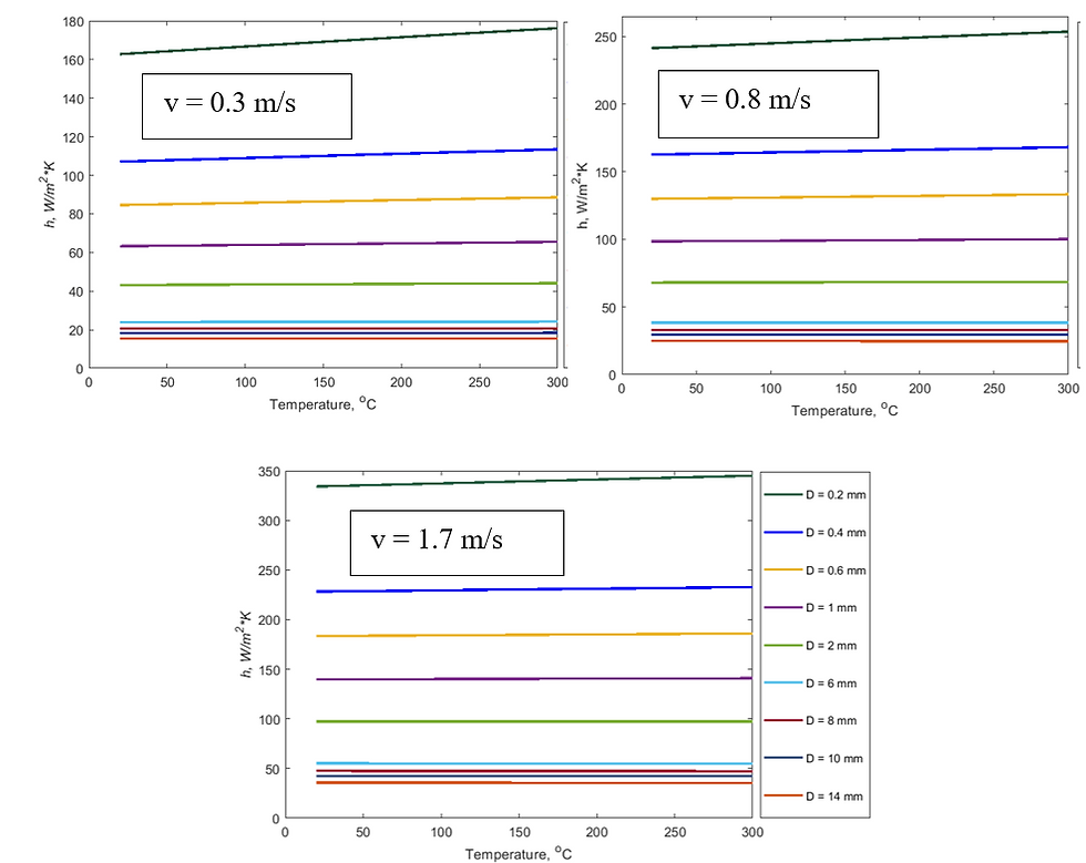
Fig. 1. Coefficient of convection heat transfer calculated for the temperature ranges from 20 to 300 oC for filament with diameter ranges from 0.2 to 14 mm corresponding to the common nozzle size of the FDM machine.
These coefficients were calculated for three selected velocities of cooling fluid for filament temperatures ranging from 20 to 300 oC and are shown in Fig. 1. For larger diameters, the changes in coefficient over the temperature were unimportant compared to small diameters. For the smallest diameter (0.2mm) where the changes in convection coefficient are expected to be the largest, these differences between the two extremes of temperature are 7.6%, 4.8%, and 3.1% for the selected velocities of 0.3, 0.8, 1.7 m/s, respectively. One can conclude that these differences are insignificant and neglect the effect of temperature for diameters larger than 0.6 mm. We considered the average values of the hconv as listed in Table 56 for further analyses in this dissertation.
Figure 2 illustrates changes in the average of coefficients of heat convection for different velocities and diameters. It is possible to fit curves to this data, as illustrated in Fig. 2.
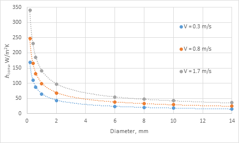
Fig 2. Curve fitting of the coefficient of convection heat transfer calculated for the temperature ranges from 20 to 300 oC at three different flow velocities for filament with diameter ranges from 0.2 to 14 mm corresponding to different common sizes of the nozzle in FM machines.
Estimation of the coefficient of forced convection for cylindrical 3D printed objects
We also analyzed printed components that had diameters between 1 to 500 mm. We calculated the hconv for seven different diameters as the upper, lower, and middle values of the three ranges. The results are shown in Fig. 3. Each of these three graphs is associated with one of the selected velocities (i.e., 0.3, 0.7, and 1.3 m/s).
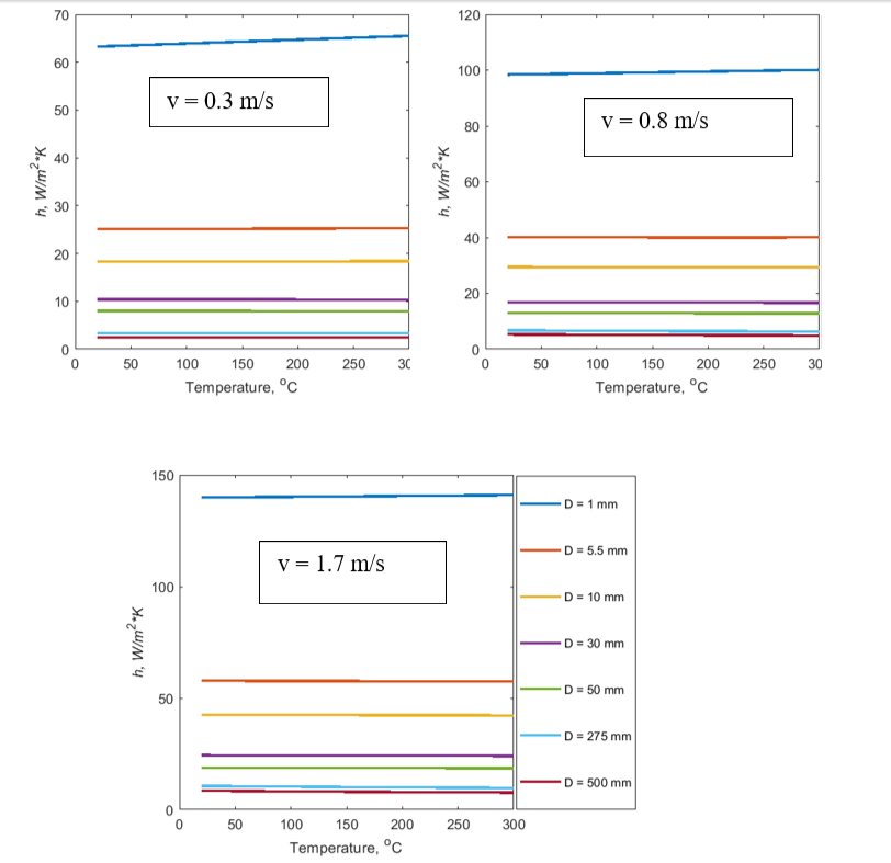
Fig 3. Coefficient of convection heat transfer calculated for the temperature between 20 to 300 oC for component with diameter ranges from 1-10, 10-50, and 50-500mm.
Because of the significant changes in the diameter, these data were not inclusive; however, we decided to use them to perform curve fittings, and the results are illustrated in Fig. 4.

Fig. 4. Coefficient of convection heat transfer calculated for the temperature ranges from 0 to 300 oC for components with diameter ranges from 1-10, 10-50, and 50-100mm.
Estimation of the coefficient of forced convection for a flat surface
In addition to objects with cylindrical shapes, we also studied flat surfaces by using the same length scale used for cylinders. The correlation proposed by Churchill and Rose, which was accurate for all Prandtl numbers was used:

The following figure, Fig. 5, depicts the changes of hconv over the range of temperature for different sizes and velocities.

Fig 5. Coefficient of convection heat transfer calculated for the temperature ranges from 20 to 300 oC in flat surfaces with length ranges from 1-10, 10-50, and 50-1000mm.
Comparing the change over the temperature indicated error up to ±3%. This data was used for curve fitting for each velocity, as shown in the following Fig. 6.
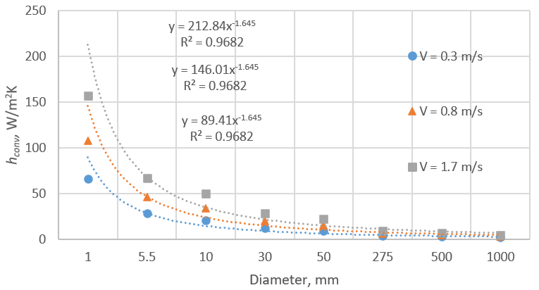
Fig. 6. Curve fitted graphs for the coefficient of convection heat transfer obtained for flat surfaces.
Estimation of the coefficient of free convection
Free convection is more perplexing than forced convection because thermal inertia, fluid viscosity, buoyancy forces, and conduction in the fluid are entangled in free convections. Thus, gravity and change in density due to variations in temperature have to be accounted for. For these analyses, following the procedure above, we needed to study cylindrical and flat surfaces separately. Although the correlation for the flat surface could be used for a cylindrical object, the diameter to height ratio (D/H) might alter this estimation. This variation is because of the transversal curvature effects in a slender cylinder.
Flat vertical surface
One of the well-known correlations for flat vertical plates was obtained by Churchill and Chu. This correlation is accurate for all Prandtl numbers within the Rayleigh number of 0.1 to 10^12:

The following figure, Fig. 7, depicts the changes of hconv over the range of temperature for different lengths.

Fig. 7. Coefficient of free convection heat transfer calculated for the temperature ranges from 25 to 300 oC for a flat vertical plate.
The average heat transfer coefficient obtained was used for curve fitting over the plate height, and the result is illustrated in Fig. 8. This curve fitting should be used cautiously for a small height between 1 to 5 mm since the curve fit exhibited large error margins of 35 to 5%; however, above 5.5 mm, the error is significantly lower (<2%).

Fig. 8. Curve fitted graph for the coefficient of natural convection heat transfer calculated for the vertical flat surfaces ranges from 1-10, 10-50, and 50-100mm.
Vertical cylinder
If the ratio of height to diameter, H/D, is low, the coefficient of convection is slightly higher than the flat plate. However, if the H/D ratio is smaller than 20, the flat plate approximation can be used to obtain the convection coefficient. Otherwise, the following correlation can be used for laminar flow to correct for the effect of curvature:

where NuH-FP is the Nusselt for the flat plate and NuC-H is the corrected Nusselt for a curved surface. In general, application for 3D printing, fabrication of slender parts is avoided. Thus, it is safe to use the approximation of the flat vertical plate for cylindrical components, except for filament or diameter smaller than 3.0 mm.
The effect of radiation heat transfer coefficient
We estimated the effect of radiation for different emissivity at different temperatures, as shown in Fig. 9.

Fig 9. The equivalent coefficient of convection heat transfer for radiation for the temperature ranges from 20 to 300 oC, assuming three different emissivities of the surface as 0.7, 0.8, and 0.9.
The equivalent convection heat transfer coefficient intensifies from 4 to above 12 W/m2K as temperature increases from room temperature (20oC) to 300oC. Comparing these values with the estimated coefficient of heat transfer shown above, confirms the significance of the radiation specifically for large diameter or length (above 50 mm) when the medium velocity is less than 0.8 m/s. Thus, it is crucial to take into account the radiation influences in parts that have a size larger than 50 mm and that are fabricated with a machine without an enclosed cooling feature, for example, BAAM machines.
We argue that, although for filament level and top layer, the effect of radiation is negligible, for other layers, the effects of radiation have to be considered. Finally, we suggest including the equivalent coefficient radiation and define a term total heat transfer coefficient (THTC) in numerical analyses.
References:
[1] Pooladvand, K., 2019, "Multifunctional Testing Artifacts for Evaluation of 3d Printed Components by Fused Deposition Modeling," Worcester Polytechnic Institute, [Link].

Comments