Principle of thermography and IR imaging in AM, How to calibrate an IR camera and selected material?
- Koohyar Pooladvand

- Jul 4, 2021
- 5 min read
Updated: Aug 18, 2021
Temperature and cooling rates, as reported in several studies, play crucial roles in the additive manufacturing processes, and measuring them can provide substantial information for predicting the material and part characteristics. AM processes are vigorous, and dynamics, which conventional accurate measuring techniques such as thermometer, thermocouple, and thermistor are not practical solutions. Thus, the non-contact methods, i.e., Infrared (IR) imager, pyrometer, laser absorption spectroscopy, and photodiodes are better choices. Non-contact methods usually rely on quantifying the received radiative energy to predict the source temperature and require accurate knowledge of the transmissivity, emissivity, and absorptivity of a surface of the source and the participating media, if any. These characteristics vary depending on temperature and color.

Thermal imaging needs to account for emissivity and absorptivity of materials at elevated temperatures. Although these values for the variety of materials are available at room temperature, including polymeric materials used in FDM, the magnitude and changes in elevated temperature require further investigation specifically for one of the widely used polymers known as ABS specifically between 40 to 200oC which is critical to the bond formation and welding of the polymer, which eventually defines the mechanical strength of the printed components. Knowing emissivity allows to map the corrected temperature in full-field measuring tools like IR imager, in-situ, and helps monitor the thermal flow accurately.
Principle of thermography by Infrared camera
IR cameras are devices that receive emitted energy from an object of interest and convert them into images. The color and contrast in these images are based on the amount of energy received. The sum of the absorption, reflection, and transmission of radiative energy from each surface is equal to the total incident radiative flux. The IR cameras’ detectors measure radiosity, which is a sum of reflection and emission from a particular surface. In addition, the emissivity and transitivity of the media between the source and the detector affect the temperature measurements. In theory, the total received energy contains emission from the object, reflections of other sources, losses due to transmission through, and emission of the participating media. For an object located in the atmosphere, the total energy received by the camera detector is defined as:

where E is radiation flux, τ transitivity, ρ reflectivity, and ε emissivity and subscripts tot, obj, atm , and sur denote total, object, atmosphere, and surrounding, respectively. Kirchhoff theory states for each surface the absorptivity, α, is equal to emissivity, ε, in its equilibrium condition. In addition, one can conclude ρ=1- α for opaque surfaces. The atmosphere also is a transparent medium thus, ε=1-τ. Finally, Eq. 1 is rewritten as:

When the distance between detector and source is less than a meter, the effect of media can be ignored [150], and therefore τatm is equal to 1.0 and Eq. 2 is simplified to:

The camera detector receives Etot and uses the integrated lookup table to determine the temperature by knowing the emissivity, humidity, and distance. However, if these parameters are not defined correctly, the IR imager generally assumes the case of a blackbody object and estimates the temperature accordingly. This process leads to an incorrect estimation of the temperature and undervalues the readouts. By knowing the ε, these inaccurate readouts can be corrected either during or after recording the measurements.
IR camera calibration and analysis
An IR camera can be calibrated by first establishing a reliable measurement reflecting the correct temperature, and second, using the calibrated camera to measure the emissivity of different colored ABS.
The energy received by a detector of a thermal imager can be merely representative of blackbody radiation if one can assume the emissivity of the object of interest is 1.0, and the effect of participating media is negligible. in this case, one can employ a calibrated blackbody and keep the distance between the thermal imager and the blackbody short, to satisfy both criteria. Therefore, the total energy received by the detector is equal to:

If the employed thermal imager is an IR camera with a broad spectrum sensitivity in mid-infrared regions (7-18 μm), the relationship between a camera’s readout and temperature can be defined mathematically as a power function explained in Eq.2. This function has been chosen knowing that the blackbody total emissive flux follows a power function in a wide spectral range:

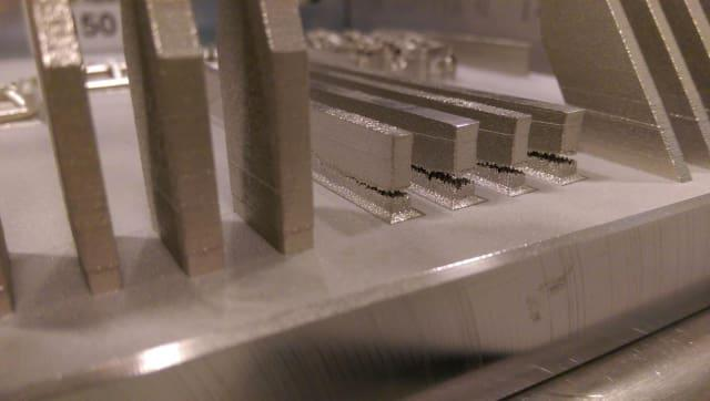
in such a calibration process, on can start with a thermal imager under an environment similar to a normal camera’s working conditions. Figure 1 shows such a setup used for calibration. The set-up consisted of an IR camera, computer platform, and calibrated blackbody. The temperature of the blackbody changed from 45 to 345oC, both ascending and descending. One can record the room temperatures regularly.

At each step, the camera recorded thermograms similar to the one shown below, and the data associated with the Area Of Interests (AOI) were stored for further analysis and curve fitting using MATLAB®. Such an experiment is done and the curve fitting results show a strong correlation with the coefficient of determination (R2) being above.

Following figure shows the fitted lines, and following table lists the results of curve fitting. One can do the curve fittings, assuming the temperature in Kelvin and degrees centigrade. Comparing the fitted curve with the camera’s readout at low temperature, particularly close to room temperature, showed the accuracy of the degree oC fitted curve was more than the Kelvin fitted curve.


Fig. 3. The acquired data for blackbody and washers and snapshot of the IR camera: (a) three measurements of the blackbody with temperature ranging between 25 to 345 oC with the curved fitting based on K and oC; (b) the response curve of the blackbody juxtaposed with the nine measurements on the washers with temperatures ranging between 45 to 200oC; and (c) a representative snapshot of the IR camera showing the different AOIs used for analyses.
After measuring the camera’s response curves, one can estimate the emissivity of the 3D printed ABS object. Images and temperatures were stored and later used in Matlab for data analysis and curve fitting. One can estimate the emissivity at various temperatures using Eq. (3) by knowing Etot from the IR camera’s readout and from the blackbody response at the specific temperature. In this equation was plugged in based on the room temperature measurements.


Fig 4. The estimated emissivity based on the gathered data and fitted curves: (a) scatter plot shows the determined emissivity values of the nine different washers indicating a similarity in trends and effects of the colors; and (b) the entire pool of data for all measurements and the polynomial fitted curve showing the trends and the estimated values.
The total irradiances off the surface of interest can be measured in camera counts within the 16-bit bandwidth. The difference between a blackbody and the 3D printed object readout increases as the temperature increases, which indicates that at higher temperatures, the emissivity of the 3D printed object decreases.
The emissivity is determined and shown in Fig. 4 . The emissivity, in general, follows a decreasing trend as temperature increases. The measured emissivity in room temperature was approximately 0.89 to 0.92, which is within the expected value for non-conductive materials (0.90 to 0.97). The emissivity drops to 0.82 as temperature ascends to 200oC for white ABS.
Figure 4 also illustrates all the measured points of the samples. A polynomial of degree three was used for the curve fitting.
Table 2 lists the coefficients of the polynomial along with some statistical values. The curve fitting also exhibits a slowing slope in temperatures between 110 to 130oC, which is attributed to the Tg of the ABS polymer.

References:
[1] Pooladvand, K., 2019, "Multifunctional Testing Artifacts for Evaluation of 3d Printed Components by Fused Deposition Modeling," Worcester Polytechnic Institute, [Link].

Comments